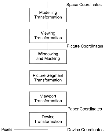
When a graphics device is first nominated, GINO defines a default paper coordinate system which consists of the default drawing area measured in millimetres with its origin at the bottom left corner of the drawing area. At this point, the user may alter the paper (or drawing) units and drawing limits before drawing commences (see Graphics Devices). The transformation between paper coordinates and device coordinates is defined within the current device driver and cannot be changed by the GINO programmer.
Once a device has been initialized, the user may define a viewport, which will set up a mapping between picture coordinates and the devices' paper coordinates (see Mapping). All drawing operations will then operate in picture coordinates. The mapping may define any range of picture coordinates which are to be displayed over a portion of the drawing area defined in paper coordinates. All windows and masks are defined in picture coordinates. The viewport mapping may be redefined at any point within an application. At this point the user is still operating in a 2D coordinate system (although a notional Z coordinate can exist, but is effectively ignored) but the origin may exist on or off the drawing area.
In order to operate in a fully 3D coordinate system, a modelling and/or viewing transformation may be defined, setting up a new space (or world) coordinate system (see 3D Transformations). All output primitive coordinates are then mapped to picture coordinates (2D) through the current modelling and viewing transformation matrices and then clipped to the current window, mask or viewport boundary before being transformed again according to the current viewport mapping.
Picture segment transformations, where appropriate take place between clipping and viewport transformation (see Segments).
The pixel input and output routines (see Image Handling) operate in device coordinates and are therefore completely independent of the GINO pipeline. In addition to these, two routines have also been provided, which set the character size (gSetCharSizePoint()) and line width (gSetLineWidthPixel()) in device coordinates. These are useful if the user wishes to control such output at the device level without interferance from the current viewport or scaling.
The figure below shows the GINO pipeline in a diagrammatic form.
 |
GINO Pipeline |